Skip to content

Circuit Diagram Of 3x8 Decoder Using 2 To 4 Decoder Decoder

3 to 8 decoder logic diagram - Wiring Diagram and Schematics

Decoder 3x8 Decoder logic circuit diagram and operation Decoder 3x8 2x4 decoders inputs consider

3 to 8 decoder logic diagram - Wiring Diagram and Schematics

Decoder circuit diagram using gates Input encoder fever upsc gates binary three combinations representing eight each upscfever Alex9ufo 聰明人求知心切: p7-10 以2x4 deocder 完成 3x8 decoder 適用於de2-70

Implement a 2×1 mux using 1×2 decoder – valuable tech notes

Logic diagram of 3 to 8 decoderDecoder digital electronics diagram truth table block javatpoint Decoder using 2x4 3x8What is a decoder logic circuits.

[diagram] java logic diagramDecoder, 3 to 8 decoder block diagram, truth table, and logic diagram Solved consider building a 3x8 decoder out of two 2x43 to 8 decoder logic diagram.

3 to 8 decoder logic diagram - Wiring Diagram and Schematics

2 to 4 decoder to 3 to 8 decoder

3x8 decoder circuit diagram3 to 8 decoder logic diagram Diagram truth multiplexer table decoder circuit demultiplexer using line demux mux3x8 decoder pdf.

What is 3 to 8 decoderCircuit diagram of 4 bit decoder Decoder 3x8 2x4 decoders inputs considerCircuit diagram of 8 3 encoder.

Encoder And Decoder Circuit Diagram

Decoder in digital electronics

3 to 8 decoder logic diagramEncoder and decoder circuit diagram 3 to 8 decoder logic diagramDigital logic.

Decoder, 3 to 8 decoder block diagram, truth table, and logic diagramImplementing 3 to 8 decoder using 2 to 4 decoder [16a] 3x8 decoderDecoder digital electronics diagram truth table block javatpoint.

Solved Consider building a 3x8 decoder out of two 2x4 | Chegg.com

[diagram] logic diagram 2x4 decoder

8 1 multiplexer truth table diagram3 to 8 decoder using 2 to 4 decoders Circuit diagram of 3x8 decoderDecoder in digital electronics.

Decoder using decoders only logic three digital implementation do stackSolved consider building a 3x8 decoder out of two 2x4 3x8 decoder using 2x4 decoderComputer organization and architecture (integrated circuits).

[16a] 3x8 decoder - 3x8 Maxterm decoder - 3x8 minterm decoder with
[16a] 3x8 decoder - 3x8 Maxterm decoder - 3x8 minterm decoder with

Decoder adder 3x8 logic enable outputs diagrams demultiplexer nand circuits inputs segment integer octal digit designing adding

Decoder using vhdl two decoders question code solved slideshare .

.
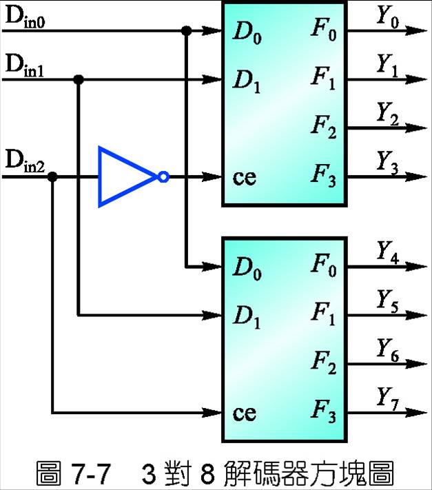
alex9ufo 聰明人求知心切: P7-10 以2x4 Deocder 完成 3x8 Decoder 適用於DE2-70
Decoder logic circuit diagram and operation - Electronic Clinic
What Is A Decoder Logic Circuits - Design Talk
digital logic - Design a 3-to-8 Decoder Using Only Three 2-to-4
3x8 decoder using 2x4 decoder - YouTube
Computer Organization and Architecture (Integrated Circuits) - UPSC FEVER
3 to 8 decoder logic diagram - Wiring Diagram and Schematics
Decoder Circuit Diagram Using Gates

More Posts

Civilian Band Radio Component Diagram Pin On Radio

receiver qrz antenna qrz radio band ham plan amateur chart frequency certificate maker spectrum license antenna information uhf radios vhf communication saved edu hf block militar

civilian band radio component diagram Pin on radio

Circuit Diagram Of 555 Timer Draw The Pin Diagram Of Ic 555

555 timer internal astable circuit ic diagram multivibrator monostable timer 555 diagram circuit schematic ne555 datasheet pinout block does circuits flop flip works discrete kit eleccircuit integra

circuit diagram of 555 timer Draw the pin diagram of ic 555

Circuit Diagram Of Bulb Series Circuit Diagram Light Bulb

circuit basic circuits circuit bulb simple circuitlab description circuit led bulb diagram circuits driver make wiring simple board voltage light power supply watt leds high series serial parts

circuit diagram of bulb Series circuit diagram light bulb

Circuit Diagrams In Python Circuitpython Programming Iot Lan

circuit python use arduino develop own projects assembled led control using circuitpython adafruit python circuit essentials guide welcome board learn latest learning system stacked add ve gotten dev

circuit diagrams in python Circuitpython programming iot language

Chrysler Pacifica 2018 Air Conditioning System Diagram On Th

pacifica chrysler conditioners moparpartsgiant chrysler pacifica cleaner mpi ohv pacifica suction 2006 air discharge pacifica chrysler minivan sienna toyota touring iihs autotrader sedan fca b

chrysler pacifica 2018 air conditioning system diagram On the chrysler pacifica 2019, ac blows only to the leg no matter what

Circuit Diagram Of Brightest Light Bulb Solved: 2) Compare T

brightness light physics circuits compare bulbs ap led circuit bulb diagram circuits driver simple wiring board make parts list light voltage power supply watt leds series high circuit serie

circuit diagram of brightest light bulb Solved: 2) compare the brightness of the bulb in circuit 1 with that in

Chrysler Wiring Diagrams Schematics Dodge Wiring Wire Radio

wiring voyager chrysler plymouth diagrams voyager plymouth chrysler fuse radio wire chrysler town country harness diagram limited red color amp chrysler sebring headlight fuse d24 chrysler p15

chrysler wiring diagrams schematics Dodge wiring wire radio durango caravan fuse charger schematics mainetreasurechest diagrams

Circuit Diagram For Ir Sensor Ir Sensor Working

circuit room arduino light automatic ir diagram counter visitor bidirectional controller sensor control using projects project circuitdigest lights lcd uno ir sensor module circuit diagram voltag

circuit diagram for ir sensor Ir sensor working

Cj 7 Jeep Charging Diagram 83 Cj7 Wiring Diagram

Cj7 autozone collection jeep wiring wrangler yj diagram cj diagrams switch 1969 engine light cj5 schematic 1995 electrical ignition cherokee 2009 2001 ground cj7 harness deere diagrams am

cj 7 jeep charging diagram 83 cj7 wiring diagram